
In principal I agree, in practice not so much. A single string of larger batteries at 24V instead of 12 would solve all of your problems, and need less attention on your part. Six 30V grid-tie panels producing about 1500W would keep them happily charged. I'd switch to 24V and get larger batteries, like L-16s. You need more capacity, and sticking with 12V is really holding you back. I think you should just gut out your existing system and start over. I'm prepared to be majorly trolled and called a moron etc which seems to happen any time I ask a question in places like this but hopefully some nice folks can correct me and help me out without going there, although I know it's oh so tempting and satisfying.). I can make up something graphical if my description sucks. So please let me know what the collective here thinks about my first couple questions and my proposed diagram. In this case, "ALL" on the selector wouldn't be helpful since it would bypass the isolator so can't think of a reason to use it, but I could still use each bank separately like I've been doing which works well for powering the fridge at night as I mentioned.

Selector switch output to inverter + and 12VDC fuse panel + input. Outputs from the isolator going to battery bank 1 and bank 2 + respectively.Ĭable from bank 1 to selector switch input 1Ĭable from bank 2 to selector switch input 2 MPPT controller and battery charger + leads connected at the input terminal of the isolator.
#Renogy battery monitor wiring diagram crack#
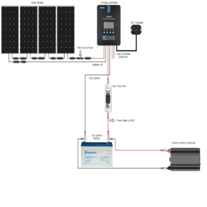
My first crack at a wiring diagram looks like (ignoring fuses/breakers & grounds for the moment, and setting aside my question on the MPPT and charger connection): My main question is how can I connect the DC battery charger/power supply to the batteries along with the MPPT controller without frying it if both are running at once? Do they have to be physically disconnected from one another (switched etc so only one or the other is charging the batteries) or can they both be connected to the batteries (at the isolator input) and charge simultaneously? Does there need to be a diode in the circuit for the MPPT controller ? Just wondering if both were connected together will the MPPT misread the state of charge in the batteries and back way off on the amps it outputs. I'd like to simplify the charging process by using a battery isolator, and also add a pair of PV panels with an MPPT controller to the system. What I'd like to do is a couple things at once. I try to alternately use each bank and let the one just charged rest before using it, not sure how much that even matters though.
#Renogy battery monitor wiring diagram generator#
Sometimes if one bank is discharged quite a bit (fridge on all night for example) and the other is still good, I'll start the generator and keep the selector switch on the bank that's low to give it maximum amps from the charger, then a few hours later switch it to "All" to top off the other bank and use that one for the night. Charger is currently wired downstream of the selector switch so that if the generator (& charger) is running and the switch is off, the batteries are disconnected completely and the charger is able to run the circuits directly. It's set up pretty simply now with a marine battery switch that ties the two banks together for charging and lets me use one or the other so one bank can be kept fresh for night time to run the fridge while the generator is off. Power for the charger comes from a gas inverter generator. An inverter runs off the batteries and feeds a couple outlets, and there are a couple of DC circuits that run directly from the batteries. Currently using a newer 45A Progressive Dynamics RV power converter/charger to charge two 12V battery banks (2 golf cart batteries each in series). I'm looking at rewiring and upgrading and old home made off grid setup in my hunting cabin to include a couple PV panels but want to revamp the way it's wired. New here so expecting to be severely roasted on this question but here goes.

Intended for use with RVs, yachts, cabins, and small to medium Off-Grid solar and UPS systems.Hi. There is also a memory function, a low voltage and capacity alert, a sleep function, and a backlight. It graphically displays the charge and discharge state of the battery, allowing users to completely grasp the battery condition, control their energy use, and plan ahead. Renogy DC 500A Battery Monitor with Shunt review The goal of this monitor is to estimate battery duration time based on current power draw and battery parameters such as voltage and current used, as well as SoC% – SoD%, by using a Shunt that calculates the quantities of electricity that pass through it and to accurately show the current state of Battery parameters.


 0 kommentar(er)
